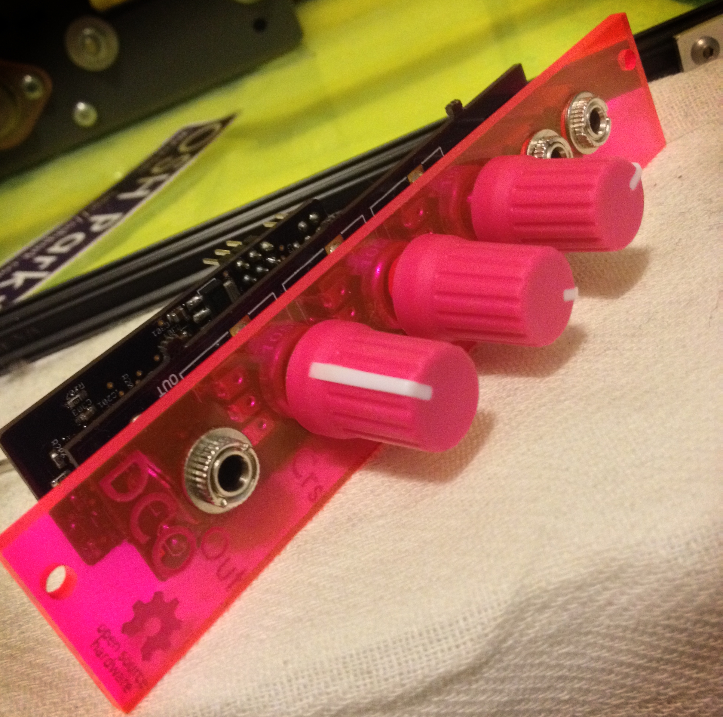
The latest installment in my open-source eurorack series (see
previous installments here and here) is an 80s-style digitally
controlled oscillator. Since a DCO is perhaps a bit less familiar than
my previous modules, I'll first describe a bit of its history and
design. If you're curious about the fabrication process or eager to
access the schematics, skip ahead to the fabrication section below.
What is a DCO?
"Digitally
Controlled Oscillator" is primarily a marketing term, so it doesn't
really have a precise technical definition. Most generally, it's an
oscillator that is somehow "more analog" than a fully digital
oscillator, where the signal is output direct from a DAC,
but yet "less analog" than a traditional VCO.
Sometimes a "DCO" is a fully analog oscillator being driven with a
control voltage from a DAC, and sometimes "DCO"
means a sum of digitally-created square waves. However, the most common
definition is the one that this module falls under: a fully analog saw
tooth oscillator hard-synced to a digital counter.
This design (which is the only thing I'll call a 'DCO' from here on
out) was first popularized by the Roland Juno series, and
became quite popular for a time, especially in low cost polyphonic analogs. During the
analog resurgance of the late 2000s/early 2010s, DCOs again became a
go-to option, appearing in the Prophet 08 and the Moog
Minitaur, among others.
DCOs have a number of differences from the "more analog" VCOs: their
tuning is very stable because the frequency ultimately comes from a
crystal oscillator. This makes them have less "analog drift", and
generally speaking this makes for better bass tones. The main price you
pay for this stability is coarser tuning - since the tone is coming from
an integer divide down of a fixed clock, there's a limited number of
"tuning steps", where an analog oscillator would have completely
continuous tuning.
How do they work?
The core of a DCO is a high speed (usually in the low megahertz)
digital clock. This clock is then fed into a counter,
which emits a pulse each time the count reaches a certain value. That
pulse then is connected to a switch that will short accross a charging
capacitor, resetting the capacitor's voltage back to zero. This creates
a saw-tooth wave across the capacitor, whose frequency is set by the
count value.
Design and Fabrication
As always, all schematics and source code are available under a
permissive license at github.
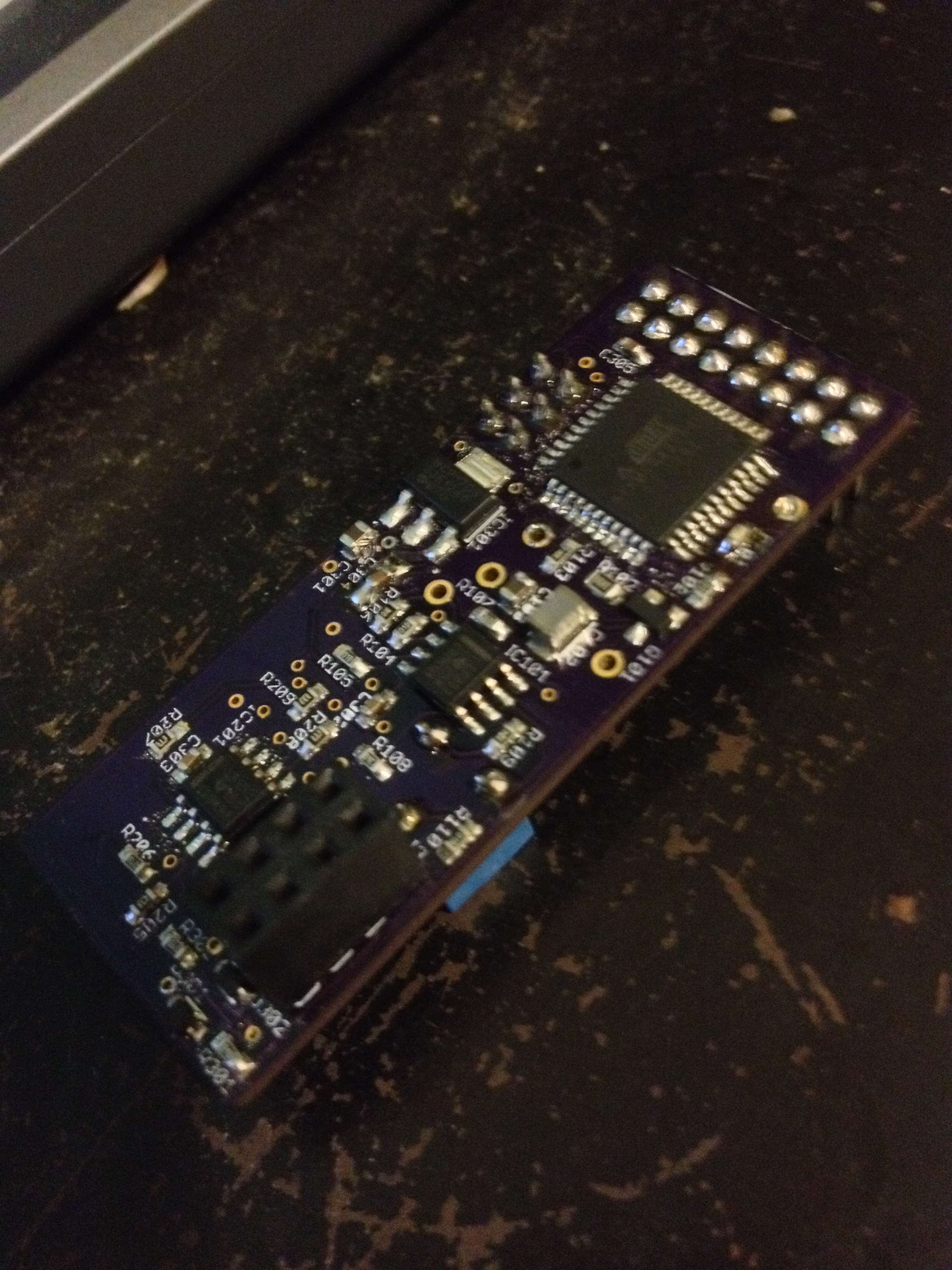
The microcontroller I used was an AVR xmega32A4U,
programmed using an Arduino port forked from the Xmegaduino project by
myself and Brendan
Powers, located here. If you're
interested in Arduino programming on the xmega, I highly recommend you
check out our port as it contains numerous bug fixes over the original,
now unmaintained Xmegaduino project.
In addition to an arduino sketch, my design includes a haskell
pre-processor to generate look-up tables for the tuning. Anyone
developing a DCO may find the code helpful.
The fabrication stack was the same as last time, that is, laser-cut
stencils from danger awesome, and
PCBs from OSH Park. Everything worked
quite well, except for the TQFN
package I originally spec'ed for the microcontroller - TQFNs are quite
hard to work with at home. If you're a hobbiest assembling boards at
home, I highly recommend choosing the much more friendly TQFP package,
if you have the option.